1 / 4
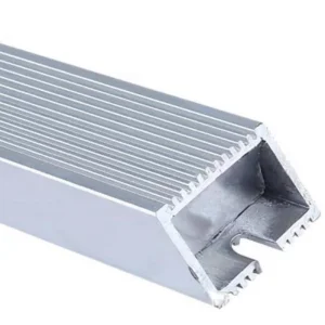
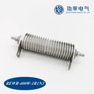
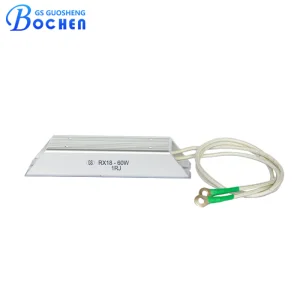
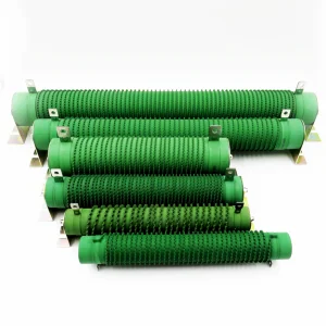
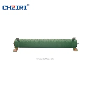
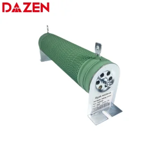
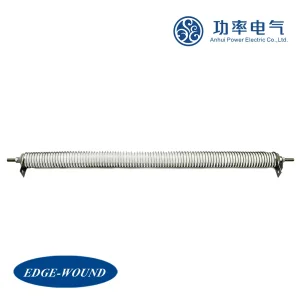
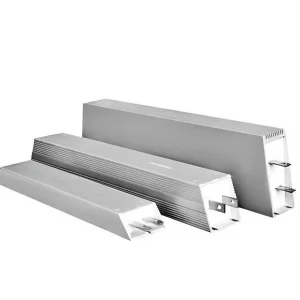
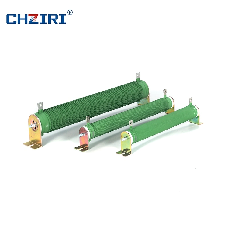
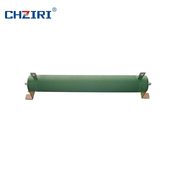
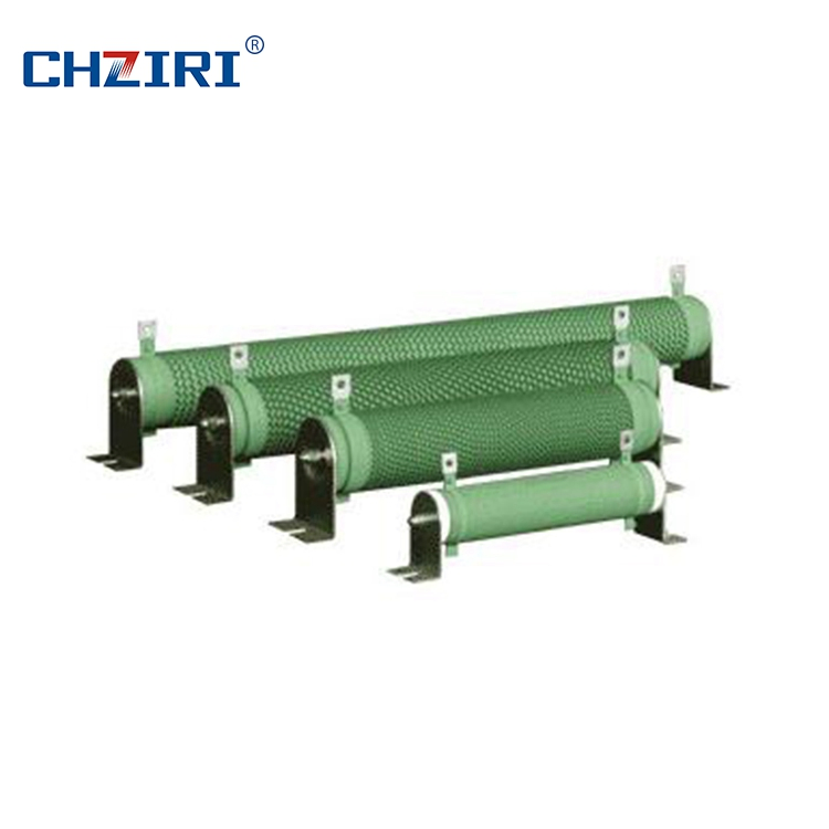
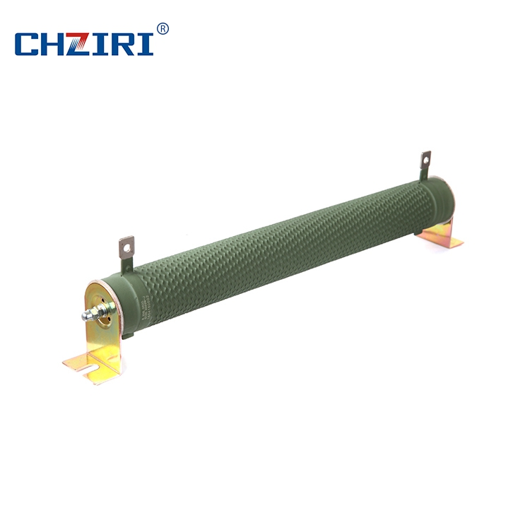
The wirewound resistor is constructed by securing two leading-out terminals onto a cylindrical ceramic tube, which is then coiled with a bandlet or wave-shaped alloy resistance wire. The surface of the ceramic tube is protected by a high-temperature resistant and flame-retardant coating. The ceramic tube serves as both the framework for the resistance wire and an efficient heat radiator.
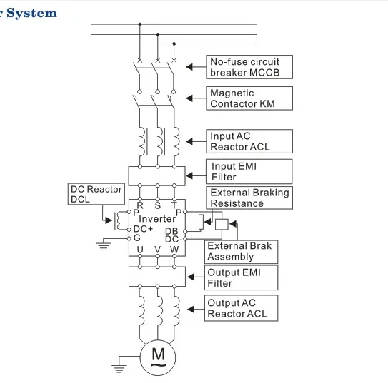
This product is highly customizable and is ideal for simulated load tests, equipment discharging, automatic control systems, and dynamic braking in transducers or inverters.
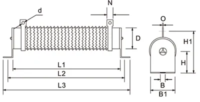
| Rated Power (W) | L1(± 2) | L2(± 5) | L3(± 3) | D(± 2) | B | B1 | H | H1(± 3) | N | d |
|---|---|---|---|---|---|---|---|---|---|---|
| 50-60 | 102 | 124 | 146 | 28 | 6.5 | 28 | 28 | 61 | 10 | 4.5 |
| 100-120 | 182 | 204 | 226 | 28 | 6.5 | 28 | 28 | 61 | 10 | 4.5 |
| 150-200 | 195 | 217 | 239 | 40 | 8.0 | 40 | 41 | 81 | 12 | 5.5 |
| 300-400 | 282 | 304 | 326 | 40 | 8.0 | 40 | 41 | 81 | 12 | 5.5 |
| 500-750 | 316 | 338 | 360 | 50 | 8.0 | 50 | 45 | 101 | 16 | 6.0 |
| 1000 | 300 | 325 | 350 | 60 | 8.5 | 60 | 60 | 119 | 16 | 6.0 |
| 2000 | 510 | 535 | 560 | 60 | 8.5 | 60 | 60 | 119 | 16 | 6.0 |
| 2500 | 600 | 625 | 650 | 60 | 8.5 | 60 | 60 | 119 | 16 | 6.0 |